Shown minus C-clip

Hose removed
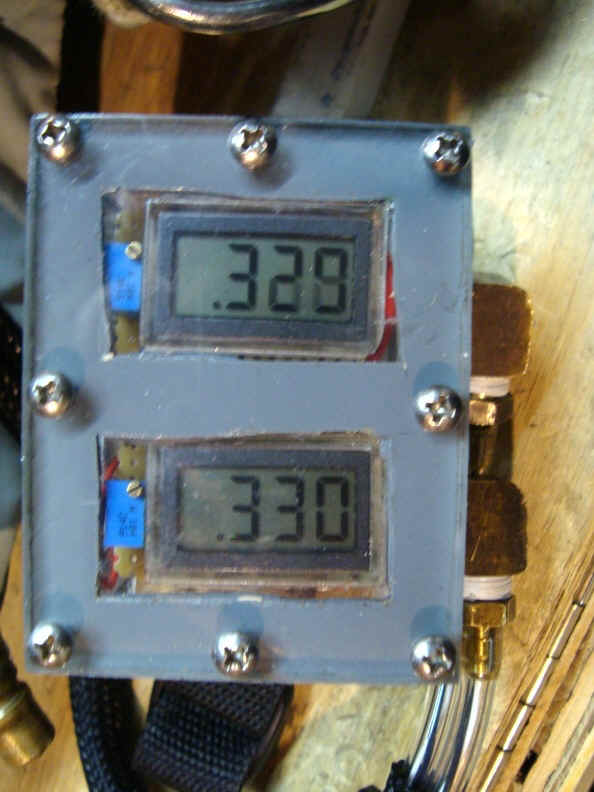
PO2 MONITOR
A VERY REAL WARNING!!!
The PO2 monitor below was developed by me for my needs. I can not and do not make any claims as to its applicability or capability to monitor PO2 values. Improper monitoring of your PO2 whilst diving a rebreather can lead to your death. There may be errors in the drawing below. Get the proper data sheets and verify your own work.
When working, the Draeger oxygauges performed well. I had heard many others complain of problems, but until recently, never had one go bad. However, I found a major flaw in their design after loosing two of them on two successive dives. That flaw turns out to be a major one.
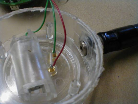
| If you remove the gauge from the boot and look at the manner of fixing the
hose to the body you will see an o-ring. The fitting is held in place by a simple c-clip.
There is a fair amount of slop at this union and water seeps around the o-ring whilst side
pressure is exerted on the hose/body connection. I applied RTV (silicone) cement to the
hose/body area. It has worked well so far. |
Shown minus C-clip |
Hose removed |
 |
The original failures were discovered when I attempted to use the oxygauges outside their boot. It seems their boot tends to add a little rigidity to the connection and keeps it working more or less, that is until you exert a sideways pressure on the gauge while you try to read it and the hose is bound up.. |
Following these failures and discovering the root cause, made me decide to make my own gauges. I knew the basic requirements as I already outlined in a previous article I wrote at www.airheadsscuba.com/sensors.html; I would require two gauges. Each gauge had to have its own supply and they had to be reliable. Last, but not least, I should be able to monitor both units simultaneously. I don't use a primary and backup unit for PO2 monitoring. I use two primaries. All the alternatives I came across cost way too much.
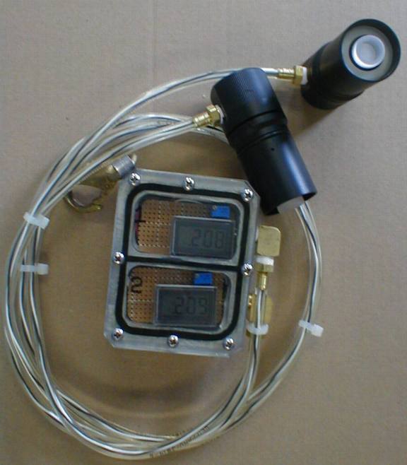
My Unit
Series II
Wrist mount unit; 89L X 63W X 48mmD |
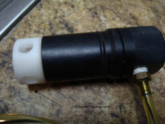
Cell caps to prevent water or a collpsed CL from blocking the cell face. |
Series II is electronically the same as Series I
below except a different housing and battery pack. We use a series of three CR2032
button batteries for the power supply. The advantage of this housing is that it is both light and is mounted on the forearm like a computer. We did give up the backlight capability due to the space available.
Yes the battery holder is indeed a paper clip. I had to come up with something as a commercially available holder we could use in the space available was not found. |
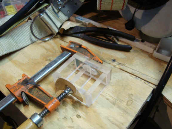
Assembly of case; note milled slot at top of clamp - This is where the reed switches are siliconed in. |
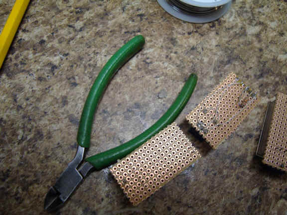
Soldering the board; we use perf board |
|
Battery holder; Paper binder, 2 lugs and some electrical tape. |
Series I
Dual gauge housing |
Housing and sensor holders |
Access to an end-mill and drill press is all you need. I started with a 50 mm X 76 mm X 100 mm (2 inch thick X 3 inch wide X 4 inch long) aluminum bar stock. I milled out the cavities to install the batteries and circuit card. I used standard off the shelf hoses, fittings and P connector housings from www.oxycheq.com. The total cost for everything was under US$200.00. That works out to a third the price of one oxygauge or a fifth the cost of a VR3. As you can see from the photos, the housing I have settled on is an ambient pressure two section housing. Each gauge sits in its own sealed pocket and has its own battery supply. I am using normally closed magnetic reed switches to switch power. Using the normally closed contacts enable me to remove a strap with the magnets attached to activate them. I installed the old tried and true barbed fittings for the polyurethane hose. I have used them on my oxygen injection system and they have never given a moments problem. There are pros and cons in an ambient pressure housing. On the plus side it is easier to make a housing that only has to withstand 70 - 140 mb (1 or 2 psi). On the negative side a flood of the case will allow water to get into the loop and a flooded loop will of course flood the PO2 gauge housing. The LCD used is nice because a flooded housing doesn't necessarily mean a fried meter. Its circuitry is epoxy encapsulated!
|
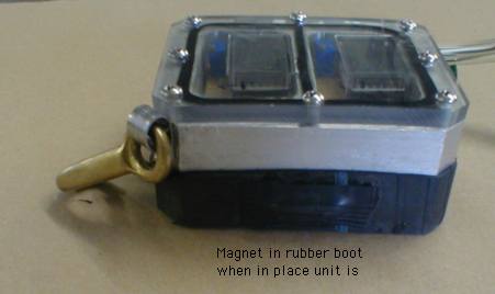
Magnetic in place |
Switch and magnet for backlight |
|
Backlight |
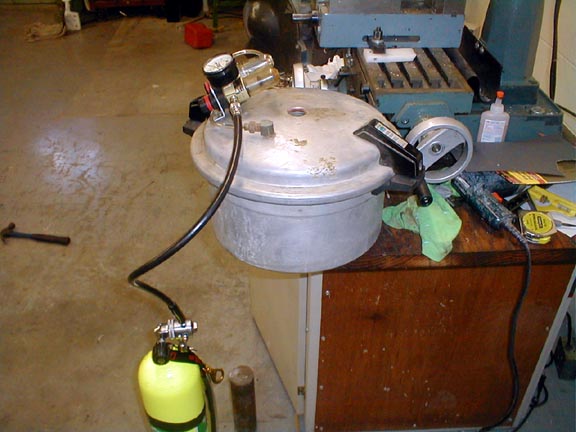
Pressure pot made from pressure cooker |
|
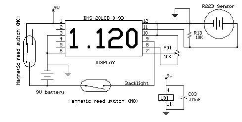
| Circuit Description
Basic PO2 gauge schematic The basic PO2 monitor is drawn right from www.ppo2.com . It is a meter, a sensor, and a potentiometer. It is an oxygen analyzer. If you do not need an audible or visual alarm, you are in business. I used a pressure pot and ran the PO2 from 0,21 ata to 1,95 ata and the oxygauge and my unit read the same all the way up! Without an alarm circuit, the power drain from the LCD meter is only about 240uA. With an alkaline 9 volt supply, a power switch really isn't necessary. A three months run time should be normal. |
||
Last update 13 Dec 2010